

A head pointer is used by individuals with limited hand or arm control to interact with a physical keyboard or a capacitive, computer/tablet touchscreen. It can also be used to manipulate objects like turning pages in a book. Head pointers have two components: a mounting system that is fit to the individual’s head and a rod that is attached to the head mount. The rod can be made of plastic, wood, or metal. The composition of the rod determines if it can only be used to depress keys on a physical keyboard and manipulate physical objects, or if it can also interact with a computer/tablet touchscreen.
Head pointers have been available for decades. They can be bulky, heavy, clunky looking, and above all, expensive. The table below contains several examples of available head pointers along with their prices. Clicking on an image will display a larger version of the image and clicking on the price below an image will take you to the web page where that head pointer can be purchased.
 |
 |
 |
| $149.00 | $149.00 | $185.00 |
 |
 |
 |
| £120.00 | $217.95 | $83.62 |
 |
 |
 |
| DIY | $91.76 | $285.00 |
 |
 |
 |
| $129.00 | €89.17 | $?? |
 |
 |
|
| $49.00 | $249.50 |
In keeping with Volksswitch’s guidelines, we only consider creating an alternative design if that design would result in significant cost savings and/or greater customization and personalization. We believe that our customizable head pointer meets both of those goals.
Our head mount can be 3D-printed for about $1.25 worth of filament. Simple elastic holds the mount in place. If you don’t need to interact with a touchscreen, a wooden dowel can be the pointer. Alternatively, a capacitive pointer can be constructed from aluminum or stainless steel tubing and a capacitive tip—both of which can be purchased online. More on that below.
The size of the head mount is customizable to within a millimeter. As with any 3D-printed device, you have access to a rainbow of filament colors. Finally, the head mount designer provides accommodations for decorating the head pointer with elements that personalize it—the head pointer above is clearly being used by a human unicorn!
The Volksswitch Customizable Head pointer is 3D-printed using flexible filament. In all of the examples shown below, the filament used was TPU. We have used PLA to print the pointer mounting bolt, but you could print that piece out of TPU as well. The head mount is printed in pieces and assembled by sliding/pressing together five dovetail joints. You may find that you can even print the head pointer on a small 3D printer if you print a single piece at a time.
First Things First:
Before you begin, you’ll need to go to the Printables page for the head pointer designer.
You’ll open OpenSCAD to create your design right on your computer. You’ll need to download the designer program, “head_pointer.scad,” from the “Files” tab. Also, download the “pointer_retention_bolt.stl” and “pointer_mount.stl” files from the same page. Then, follow these instructions to download OpenSCAD and open the head_pointer.scad file for customization.
Customizing the Head pointer:
You’ll want to go through the customizations from top to bottom of the Customizer pane. Here are all the customization categories available:

- The Part to Print category contains a single option where you select the head mount part to print. That part will then be displayed, and you can provide additional measurements. You will need to print one arm connector, one front arm, one back arm, and two side arms. You can select the pointer retention bolt from this list, but since you can’t further customize the bolt, it may be easier – and certainly quicker – to download the STL file for the bolt from the Printables page.
- The Arm Measurements category contains options to control the length of each arm. You can also specify the thickness of the arms. That value will also affect the thickness of the arm connector. Since you render and export parts one at a time, you can change the thickness with each part – or set a value and leave it alone. In that case, the arms and connector will all be the same thickness.
- The Elastic Measurements category contains options for specifying the width and thickness of each length of elastic used to join the arms. You also specify the method for attaching the elastic to the mounting points on each arm.
- The Pointer Mount Measurements category contains options for specifying the block connecting the pointer rod to the head mount. The options focus on the size and tightness of the holes and rails.
- The Accessory Hole Info category contains options for specifying where holes in the arms will appear so that you can attach decorations and other accessories to the arms and arm connector. As you’ll see below, an accessory can hold elastic in place, so an accessory hole may be part of your plan for attaching your elastic.
Part to Print Category:
The Part to Print category contains a single option. It’s a pull-down list of available parts:

The following picture identifies each of these parts:

The pointer itself and the elastic bands are not included in this list. They have to be obtained separately. See the sections below on elastic bands and options for pointers.
You can display, render, and export the pointer retention bolt as STL, but since you can’t customize it in any way, you may want to download the prepared STL file from Printables instead. The retention bolt and the pointer mount contain threaded surfaces, which take a significant amount of time to render and export.
We recommend printing all parts except the bolt from a flexible filament like TPU and the bolt from PLA.
Arm Measurements Category:

The Arm Measurements category contains multiple sliders where you record measurements of the individual’s head. Those measurements will then determine the lengths of the front, side, and back arms. There is also a measurement that specifies the angle at which the side arms come out of the arm connector. Finally, specify how thick the arms (and arm connector) should be. The thicker the arms the more rigid they will be, but also, the more pressure they will exert on the individual’s head because you’ll need stronger elastic to bend them. You should start with the default value of 2 and then make the arms thinner or thicker as necessary.
If you find that the connections between the arms and the arm connector are too loose or too tight, you can separately control the tightness and thickness of the dovetail joints. Dovetail tightness affects only the arm connector so if you change this value, you only need to print the arm connector again. While you’re adjusting this value, you can save time and filament by printing only a “dovetail tightness test”:

Look for that specialized entry in the “Part to Print” > “Part” pull-down list. The object on the left represents the arm connector side of the connection, and the object on the right represents the arm side.
Since you render and export each part individually, you can change the thickness value for each arm or the arm connector.
Taking Measurements for the Head Pointer
Finding the Origin Point
All measurements for the head pointer start at a central point (the “origin point”) on the top of the individual’s head. So, the first step is to locate this origin point. Here’s our recommendation…
Take a piece of string and run it under the individual’s chin (against their neck), alongside and parallel to their ears, until the ends of the string cross on top of the individual’s head.

They should cross a point on the centerline from the front to the back of the individual’s head. That point will be the “origin” for all measurements. The pictures below were taken from the front and back.
 |
 |
You’ll take all your measurements from this origin point. Before you remove the string, you need to get one special measurement – the angle between the centerline and the string:
 |
 |
You can use your own protractor to measure the angle, or you can print one that we’ve put in a PDF document and placed on Printables, called “head_pointer_measuring_kit.pdf” (and one called “A4 head_pointer_measuring_kit.pdf” to print on A4 paper). If you print a protractor, it helps to cut out a center hole that you can easily place over the “origin point”.
The value you measure on your protractor will be the “temple angle” value.
Don’t lose the location of the origin point when you remove the string. It’s key for at least three more measurements.
Measuring the Arms
The first thing to recognize is that there are two fundamental versions of the head pointer. Version number one is small and limited to approximately the same size as a baseball cap:
 |
 |
This version has only two elastic bands, one at the bottom of the hat and the other around the chin.
The second version is longer on the sides and in the back:
 |
 |
This version allows for a third elastic band that extends from each side, below each ear, and around the nape of the neck. The second version is more stable than the first version.
Both versions measure the front arm in the same way: from the origin point to the brow ridge.
For a side arm, the short version requires measuring from the origin point to the top of the ear. You will set the measurement for the bottom of the ear to zero. If you want the longer version, you measure to the bottom of the ear as well. You only specify the measurements for a single side arm, but you will print two.
For a back arm, the short version requires that you measure to the point on the back of the head where the individual’s skull starts to curve back forward. You will set the measurement for the base of the skull (i.e., the start of the neck) to zero. If you want the longer version, you will measure to the start of the neck.
As stated above, the thicker an arm, the more rigid it will be, but also, the more pressure it will exert on the individual’s head, the more rigid the elastic band will need to be. You should start with the default value of 2 and then make the arms thinner or thicker as necessary. You can also control the rigidity of the arms and arm connector by varying the infill percentage, the number of shells, the number of top and bottom layers, and even the geometry of the infill. There’s nothing to stop you from specifying arms with different thicknesses in the same head pointer.
Tools for Measuring
You’ll find it very difficult to use a ruler to take these measurements. Simply because you’ll need to bend the ruler around curves in the individual’s skull, your best choice will be a soft tape measure—preferably one that has a metric side since the numbers you enter into the designer are all in millimeters.
If you don’t have access to a soft tape measure – even one in inches – you can use the second part of the head pointer measurement kit. It’s just a blank ruler that you cut out of the paper once you print it:

Once you print and cut out the blank ruler, cut or punch out a small opening around the “reference point” on the ruler. Place that opening over the origin point and then rotate the paper ruler to the various points you want to measure; make a small mark on the ruler’s edge each time (preferably with a description of what that mark means). Then, lay the paper ruler against your official ruler and read off the values for the marks you made with the zero of the ruler on the line associated with the reference point:

Then read where the marks on your paper ruler fall:
![]()
This video demonstrates how to collect these measurements.
Elastic Measurements Category
You can select different sizes of elastic and different mounting methods for each type of band.

The width and thickness measurements ensure that slots “cut” in the arm will be large enough for the particular elastic you choose. If you decide to attach the elastic to the arm via a post, then the thickness is ignored. The width is still used to determine the location of the post.
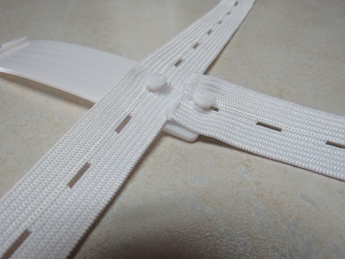
For each band, you can tell the designer how you want to attach the elastic to the arm. There are three types in each case:

As you’d expect, a double slot attachment type puts 2 pairs of slots at that location on the arm:
 |
 |
This type of attachment works well with simple bias tape but takes more time to set up.
Terminating the elastic, as in the picture on the left, so that it holds tight can be confusing. This picture demonstrates how you should weave the elastic through the two slots:

“Post” is the default attachment type. Posts are perfect to use when using elastic with button holes. It’s strong and very easy to attach/detach:
 |
 |
If you choose “none” as the attachment type, the designer won’t put a post or slots in that location on the arm. Clearly, you need some way to attach the elastic so you won’t stop at this point. Instead, you’ll specify a hole for a decoration.
Pointer Mount Measurements Category:
The Pointer Mount Measurements category is focused entirely on the pointer mount. There are three options that specify how the pointer will attach to the mount and how the mount will attach to the arm connector:

Let’s look at the features of the pointer mount:

The “pointer diameter” option will affect the diameter of the pointer hole. You can set the diameter to whole millimeter values. However, you can further control the diameter of the pointer hole by setting the tightness of the hole. Setting “pointer tightness” to negative values makes the hole diameter slightly smaller, and positive values make the diameter slightly larger.
Note that you can, and probably should, make the pointer hole a little larger than the diameter of your pointer. The pointer hole will probably be a bit smaller than you specified simply because of how the mount is oriented during printing. If the mount is printed out of a flexible filament, it will provide sufficient friction to hold the pointer tight once the pointer retention bolt is in place.
You can control the angle at which the pointer sits in the mount. Adjusting the angle may reduce the amount of head movement the user requires to indicate their specific choice.
 |
 |
| 0-degree pointer angle | 15-degree pointer angle |
The “pointer retention bolt tightness” option affects the diameter of the threaded hole for the retention bolt. Flexible filaments have inherent friction, so this option controls how easy or hard it is to screw in the retention bolt.
The “pointer mount tightness” option affects the width and height of the pointer mount dovetails. You want your pointer mount to fit tightly into the rails on the arm connector, but you also want to be able to slide it forward and backward along those rails (with some force) so you can adjust the angle of the pointer with respect to the individual’s head.
The two “tightness” sliders range from -9 on the left to +9 on the right. The more positive the value, the tighter the interface will be, and the more negative the value, the looser the interface will be.
As the comments above the options say, these values affect only the pointer mount. So, if you change one or both of them, you only need to reprint the pointer mount.
You can use the head pointer to hold a laser pointer. There are lots of laser pointers available for playing with pets that work well with a head pointer. Our favorite is this 3-pack. The advantage of these pointers is that they are devoted to generating a laser beam and don’t try to provide a spotlight as well. Even more important, they take standard AAA batteries rather than cell batteries, so you get longer battery life, and the batteries can be replaced more easily and inexpensively.

The laser pointer has a small button on the barrel, which you press to turn on the beam. When you release the button, the beam turns off. You should position this button in the hole for the retention bolt:
You can use the retention bolt to depress this button and hold the pointer in place simultaneously. Unscrew the bolt slightly to turn off the beam:

To make it possible to slide the laser pointer, with its button, into the mount, you add a slot above the pointer hole. The height and width of the slot should accommodate the button:

Accessory Hole Info

This is where the options get fun! With these options, you can put holes of various sizes at any location along the front, side, and rear arms as well as along the center line of the arm connector.
Speaking of the arm connector, if you need to measure for an accessory hole after you’ve already printed a complete headset and can no longer remember where the origin point is located, it’s actually preserved on the arm connector. Look for a small hole at the center of the four arms:

Start your tape measure at this point and measure along the arm to the point where you’d like to place the accessory hole. Look for the pair of square brackets under the arm’s name where you’d like the hole to go and put the measurement there. If you want more holes in the same arm, just put a comma between the numbers.
The last thing you need to do is decide on the diameter of the hole(s). You can put holes in any or all of the arms. You can also put holes in the arm connector from the origin point on backward.
What do you do with the holes?
Answer: be creative. Here are a couple of ideas…
Plastic Rivets
You can purchase a bag of plastic rivets for a few dollars, and they’re great for attaching plastic (3D-printed, maybe?) items to the head pointer:

You’ll be told the hole size into which these are normally inserted. You make the hole in the arm the same size. Then, you must put a similarly sized hole in the plastic item. If you find an item online that you’d like to use to decorate the head pointer, you can use a tool like Tinkercad to add the hole to an STL file.
Consider a cut in the base of the object that looks like this in cross-section:

The “A” dimension is the overall width of the point of the rivet. The “B” dimension is 2 mm. The “C” dimension is the same as the diameter of the hole you put in the arm.
The assembly looks like this:
For the unicorn pointer above, we start by putting a hole in the back arm, inserting a plastic rivet, printing the tail (borrowed from a horse we found on Thingiverse, adding a hole at the base using Tinkercad, splitting lengthwise in the slicer to reduce the need for supports, then printed both halves and glued them together), and lastly, the tail was pushed onto the rivet:
 |
 |
 |
|

The unicorn horn was assembled the same way except that the hole was put at the end of the front arm, and the rivet was used to anchor the elastic band at the front:
 |
 |
 |
 |
 |
|
Snap Buttons
Snap Buttons are an inexpensive way to create a head pointer whose decorations can be changed by snapping on and off small objects.
Here, we’ve designed the side arms with a pair of 2 mm holes on each side. In addition, the side arms are only 1 mm thick. This is because the snap buttons are relatively small, and the rivet component can’t reach completely through a 2 mm thick arm. To compensate for these arms being thinner, we made the arm connector, front arm, and back arm 3 mm thick.
We’ve chosen white snap buttons so they don’t stand out against the white of the head pointer. Last, we “borrowed” puppy ears from a Halloween costume and put the other halves of the snap buttons (yellow ones) in them.
 |
 |
 |
 |
Now we just snap on the ears at different locations for different effects:
 |
 |
| “perky puppy” | “pokey puppy” |
We’re sure you can be much more creative!
Creating a Capacitive Pointer
If you’re interested in how a capacitive pointer/stylus works, read more about it here.
When we first saw the head pointer from ShapeDad, we were surprised to learn that a capacitive pointer/stylus doesn’t necessarily have to contact a person’s skin to reliably control a touchscreen. After exchanging some direct messages, we purchased just the pointer from ShapeDad and discovered that it is just a stainless steel tube with a conductive mesh tip. Aluminum tubing also works.
It appears that there has to be enough mass or surface area in the tube for it to serve the same function as a person’s skin. We’ve struggled a bit to find options for low-volume (i.e., just one) ways to buy metal tubing, but here are a couple – both from McMaster-Carr:
- Welded Stainless Steel Tubing, Straight, 6 mm OD, 0.5 mm wall thickness, 0.5 meter long
- Multipurpose 6061 Aluminum Round Tube, 0.035 wall thickness, 1/4″ OD, 2 feet long
A Conductive Tip
The ShapeDad pointer comes with a “conductive plug” at the end, and you can purchase two more for $20:

They appear to be very sturdy, but they are bulky and make ineffective contact with the touchscreen. You can get much less expensive and much more effective conductive tips online. Here are a set of 8 tips for $9:

Note that we found that the opening in the stainless steel tube from McMaster-Carr was too wide to allow the tip to be screwed in, and we had to epoxy it in instead. The aluminum tube opening was too narrow, and we had to read it out before we could screw in the tip. The optimal solution would be to use a tap to add internal threads to the tube.
Bending the Pointer
Another thing we learned from the ShapeDad pointer is that it has a flattened region near the tip:

The flattened region is about 25 mm long and starts about 100 mm from the end of the pointer.
If you need to bend the pointer so that the tip engages with the touchscreen at the best angle, you’ll find it much easier to bend the pointer in this flattened region than where the pointer is still round.
Using a vice or vice grips, you can create a flattened region like this in your tube. If you’re a blacksmith at heart, you can probably accomplish the same thing with a hammer.
The Customizable Head Pointer in Action!
In the picture below, Liam uses a double-mount version of the head pointer to participate in a big boccia competition in Montreal, Canada.


