
You’re here because you’ve started running Voice It assembly test 3, and in step 7 you bring the sample RFID tag near the RFID reader card and nothing displays in the Serial Monitor window.
You’ve already visually checked your wiring and the seven jumper wires are inserted into the proper terminal block gates and are attached to the correct pins on the RFID card.
In this special test you’re going to check the continuity all the way from the Arduino to the female ends of the seven jumper wires.
- Begin by detaching the USB data cable from the underside of the Voice It.
- Remove all jumpers from the pins of the RFID reader card (you can also leave them attached as described in the video above).
- As you look at the jumper wires from above, bend back wires 5 and 7. These are the wires that have been connected to the 3v3 and GND pins of the RFID card:

- Select a male/male jumper and attach one end to the GND slot in the fourth row (any unused GND slot will work):

- Insert the USB data cable back into the underside of the Voice It
- Hold the free end of the male/male jumper wire to the screw for port 12 on the terminal breakout board.
- Use your finger to depress and release the blue “reset” button on the Arduino board.
- Watch the Arduino IDE Serial Monitor window. You’ll eventually see the Pin Test function start.
- Text will begin to be written to the Serial Monitor window. A new line will be written every second. Eventually the window will fill up with text:

- Each line shows the current “state” of each lead. The number in parentheses after the name of the lead is the slot into which that lead should be inserted on the terminal block. The most “current” line will always be the one at the bottom of the window.
- Insert the free end of the male/male jumper into the left-most (SDA) lead of the seven leads (or touch carefully to the SDA pin on the RFID card as shown in the video):

- The last line will change to display “SDA(7) = 0”. That means that the Arduino sees that the SDA pin is now connected to ground. This verifies the connectivity of that lead all the way back to the Arduino. All other leads will be displayed as equal to “1”.

- Move the jumper to the next lead to the right and verify that the entry for SCK is now equal to “0” and all the rest register as equal to “1”:

- Keep moving to the right until you reach the RST lead. Be careful not to plug the male/male jumper into the fifth lead – the 3V3 lead:

- The Serial Monitor should now show that RST(6) has been set to “0” while all other leads register as “1”:

- Remove the male/male jumper and the leads will, again, all register as “1”.
- Repeat for all other connections to the RFID card. Avoid connecting to the 3V3 and GND pins/jumpers. Verify that the Serial Monitor displays a “0” value for the appropriate connection.
- Once the Pin Test is completed, detach the USB data cable from the Voice It.
- If you’re able to progress through each lead with the Serial Monitor changing the value of that lead from “1” to “0” as you go, then the most likely problem is that you have a bad RFID card. All we can suggest is that you order another and see if that solves the problem.
- If, on the other hand, one or more of the leads won’t change from “1” to “0” you probably have a broken jumper wire, or the other end of the jumper is not properly seated in the slot and making contact with the metal of the slot, or you have inserted the other end of that jumper into the wrong slot (check again…).
- If you find a pin or wire that just won’t respond to the test by displaying a “0”, press the free end of the GND wire directly to the screw head on that terminal block slot. This has the effect of taking the jumper wire to the RFID card out of the test and goes directly to the terminal block. If you still don’t see a “0” for that slot, verify that you’re looking at the correct slot. if the slot is correct, disconnect the USB data cable from the Voice It, remove all 4 screws holding the terminal block to the enclosure bottom, reinsert the USB data cable and repeat the Pin Test. If the test now passes, the terminal block board is damaged and will need to be replaced.
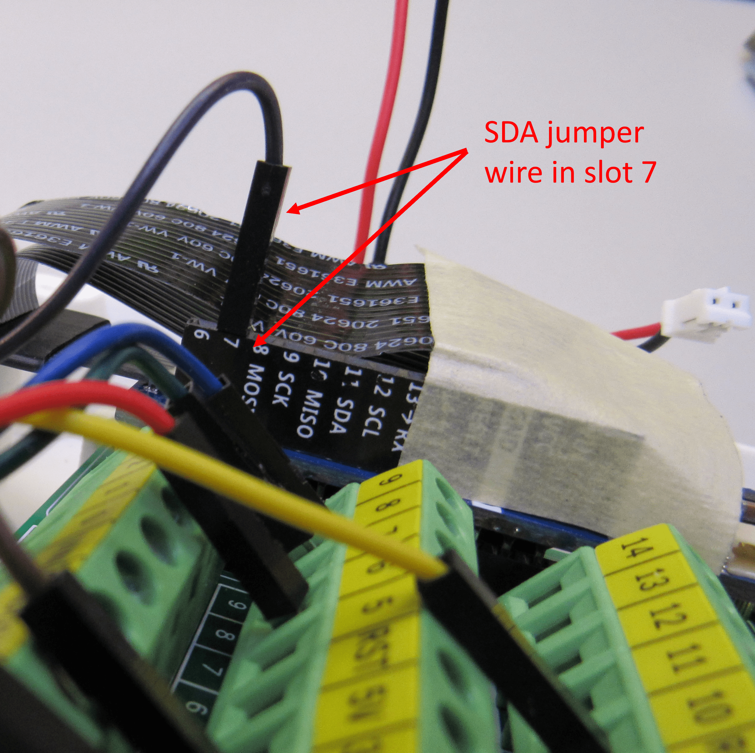
- If worse comes to worse – maybe you’re under time pressure to get the Voice It assembled – you can just plug the jumper wire associated with the problem connection directly into the appropriate slot in the header on the Arduino. For example if you can’t get the SDA connection to work, you can remove the jumper from the #7 gate on the terminal board and plug it into the #7 slot on the Arduino. Be sure to use the slot number identified in these instructions. The paint on the Arduino header shows the SDA slot as port 11. Ignore that slot and insert the jumper wire into slot #7 as instructed. This connection won’t be as sturdy as being screwed into a terminal block gate so you may need to add some masking tape to hold the jumper in place.
Once you address the problem…
- Attach the seven jumper cables to the original or a new RFID reader card if you removed them for the test.
- Connect the USB data cable to of the Voice It.
- Restart the assembly test.